Purpose
Prerequisites
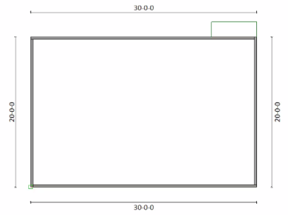
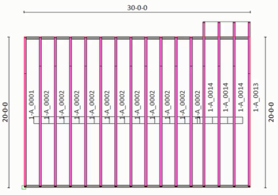
A basic layout
Steps


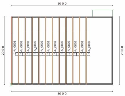
A basic, sample layout is shown below.
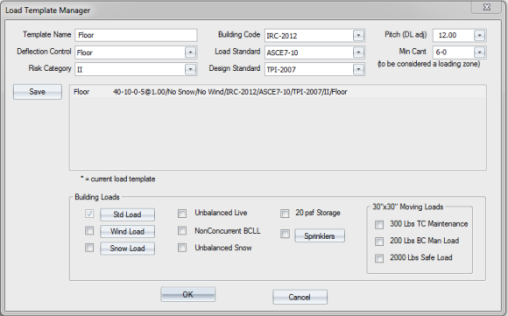
- Click Load Template Manager and make any loading changes. Click OK.
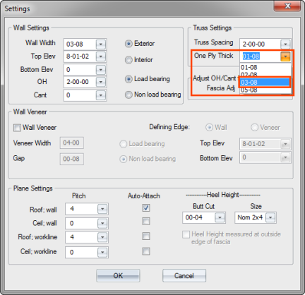
- Click Settings to edit the truss settings. For this example, select 03-03 for One Ply Thick setting and click OK.
- Select Next Truss from the Truss Placement menu or click
 to display the Next Truss dialog.
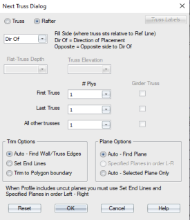
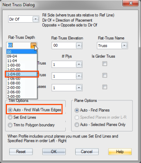
- For this example, change the Flat-Truss Depth to 1-04-00 and make sure the Auto option is selected under Trim Options. Click OK.
- Select a reference line on the layout to position trusses.
- Enter an Offset Distance and click OK.
- Select a stop point for truss placement.
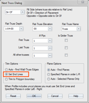
- Click Next Truss and select the Set End Lines option. Click OK.
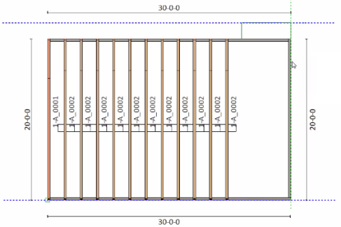
- Select the left end of the bottom chord and the left end of the top chord.
- Select the right end of the bottom chord.
- Select a reference line to position trusses.
- Accept the offset distance of 0000 and click OK.
- Select a stop point for truss placement and select all trusses.
- Click End Desc Right
 .
.
The End Desc Right dialog displays.
- Select Ribbon Post and from the Y Measure drop down list, select 03-08.
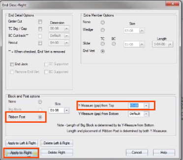
- Click Apply to Right.
- Rotate the model to see the floor truss in 3D view.